- Understanding impedance, distortion, frequency response, and harmonics is key to interpreting what the oscilloscope shows in an audio amplifier.
- With a homemade mini-laboratory (oscilloscope, generator or software and loads) you can measure input, output, THD, saturation, noise and hum in tube, transistor and class D amplifiers.
- FFT analysis and frequency response reveal the harmonic distribution and tonal behavior, but it should always be interpreted in the context of actual listening.
- The combination of an oscilloscope and free software turns the sound card into an effective audio analyzer for detecting oscillations, interference, and design problems.
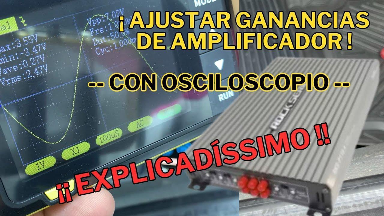
When we start tinkering with amplifiers, sooner or later we move beyond the typical "it sounds loud" and start wanting to know what the circuitry is actually doing inside . Especially when we buy a cheap Class D amplifier online or build a homemade tube amp, it's normal to wonder if the waveforms we see on the oscilloscope mean the device is good, bad, or simply "decent for the price."
Many audiophiles are surprised to see that a ten-euro amplifier bought on AliExpress displays a rather "dirty" signal on the oscilloscope, with switching residue and high-frequency noise, yet when played with real music, the sound is more than acceptable. This kind of situation forces us to understand that measuring an audio amplifier with an oscilloscope isn't just about checking if the waveform looks good , but about interpreting what we're seeing, knowing which tests are meaningful, and how to put them into context with what our ears actually hear.
Why it makes sense to measure audio amplifiers with an oscilloscope
When you're starting out in the world of audiophiles or DIY amplifier building, it's common to think that as long as something "doesn't distort to the ear," it's good enough. But curiosity soon arises to check if the amp is clipping, how much noise it introduces, how it handles different frequencies , or if it's oscillating where it shouldn't. That's where the oscilloscope comes in, along with a signal generator or, failing that, free software that acts as both a generator and analyzer.
The key is to set up a kind of home mini-lab where we can perform tests quite similar to those on a professional test bench, but with readily available tools: a physical oscilloscope (or a software oscilloscope using the sound card), a function generator or a PC that outputs sweeps and tones through the audio output, and some loads and attenuators. With that, you can obtain very useful data from any amplifier, from a high-fidelity tube amplifier to a low-cost Class D module.
Furthermore, these types of measurements help to debunk the myth that any "ugly" waveform is synonymous with bad sound. Sometimes the opposite is true: the graphs might be alarming, but the resulting sound perfectly matches what we expect from an inexpensive or entry-level system. Of course, high-end equipment does demand impeccable waveforms and distortion figures, but context is crucial.
Another interesting point is that many of these tests rely on free audio analysis software designed to work with a computer's sound card. These programs allow you to view spectra, harmonics, frequency response, THD levels, and more in a very visual way, making them an ideal complement to the traditional oscilloscope.
In short, measuring with an oscilloscope and software isn't just for engineers: any hobbyist with a little care and a willingness to learn can get much more out of their amplifiers , fine-tune designs, detect faults, and, above all, understand why their equipment sounds the way it does.
Basic concepts before connecting the oscilloscope
Before you start sticking the oscilloscope probe into any part of the circuit, it's a good idea to understand a few electrical concepts that will come up repeatedly : impedance, distortion, frequency response, harmonics, saturation, background noise, mains hum, etc. You don't need to be an engineer, but you do need to know what you're trying to measure.
In audio amplifier testing, we always distinguish between the low-frequency signal portion (the audio itself) and, in some setups, a radio frequency (RF) portion, for example, when working with amplifiers operating around 1 MHz. In these scenarios, components such as DC blockers, 50 Ω terminators, and sometimes dedicated RF attenuators are used.
In RF, the typical chain might look something like this: RF amplifier → DC blocker → 50 Ω load or terminator . Understanding the function of each component prevents costly mistakes, as we're dealing with power levels and frequencies where a single oversight can damage something in an instant. In pure audio, however, the situation changes, and instead of worrying about 50 Ω lines, we focus on input and output impedances, distortion, clipping, and noise.
Even a simple oscilloscope allows us to view waveforms over time, detect clipping, oscillations, unusual peaks, hum, or high-frequency noise . If it also has an FFT function, or if we combine it with analysis software, we can also see the frequency content and harmonic distribution, which opens the door to fairly accurate THD and frequency response measurements.
Finally, it is necessary to consider the limitations of the measuring equipment itself: permissible voltage range, input impedance, bandwidth, probe type, etc. Knowing this data is essential to decide whether we can connect the oscilloscope directly to the amplifier output or whether we need a 10:1 attenuator probe or an additional attenuator to avoid exceeding the range or excessively altering the circuit under test.
Basic tests on audio amplifiers: what is worth measuring
If you want to go beyond simply saying "it sounds good," you should consider a relatively standard battery of tests that will give you a technical understanding of the amplifier's performance. In the professional world, many parameters are measured, but with home equipment, you can focus on a few that provide a lot of information without overcomplicating things.
Among the most useful tests we find the measurement of input impedance (to know what load the signal source sees), output impedance (to understand how the speaker controls and the damping factor), impedances between stages (very interesting in tube amplifiers with several gain stages), as well as different types of harmonic distortion, both with negative feedback connected and without it.
It is also very illustrative to study amplifier saturation with a sine wave : up to what input level the signal remains clean and from what point the amplifier begins to clip. The oscilloscope clearly shows the transition from a "round" sine wave to a signal with flattened peaks, symmetrical or asymmetrical depending on the circuit design.
In addition to these tests focused on linearity, it's worth taking time to measure noise, mains hum, radio frequency interference, and any out-of-band oscillations. Many seemingly quiet amplifiers are actually oscillating in the ultrasonic range, which can heat components, cause instabilities, or interfere with other equipment, even if it's imperceptible to the ear.
Finally, frequency response and spectrum analyses can be performed , checking how the gain varies in the bass, midrange, and treble frequencies, where the level starts to drop, whether there are unwanted resonances, etc. In tube amplifiers with an output transformer, for example, these tests help to see to what extent the transformer limits the extremes of the band.
Use of the oscilloscope in RF setups: DC blocker, terminator and attenuator
When the amplifier we're working with is not just an audio amplifier, but an RF amplifier operating at around 1 MHz or higher, a number of additional considerations arise regarding impedance matching and the protection of the measuring equipment. In these cases, it's very common to find setups that include DC blockers and 50 Ω terminators at the output.
The DC blocker is installed to eliminate any DC component that might come from the amplifier and could damage both the load and downstream equipment. It is essentially a capacitor sized to operate in the desired frequency band without introducing a noticeable signal drop.
Next, an RF terminator is typically connected, usually a 50 Ω resistor that acts as a matched load . This prevents signal reflection along the line and creates stable operating conditions for the amplifier. If the system is designed for 50 Ω, using this type of terminator is practically mandatory.
The typical question is whether the oscilloscope can be connected directly to this RF line or if a specific attenuator is needed. The answer depends on the voltage level and output impedance of the amplifier, as well as the oscilloscope's channel capacity. In many cases, a 10:1 probe already acts as an attenuator and reduces the impact on the circuit , but in pure RF it is also very common to use calibrated attenuators that maintain a 50 Ω impedance match throughout the chain.
If we're using a low-cost amplifier to work with expensive equipment , it's essential to know the maximum voltage the stage can deliver, the type of load it's designed for, and the limitations of our oscilloscope. From there, we can decide whether an attenuated probe is sufficient, whether a fixed attenuator of, for example, 10 dB or 20 dB is needed, or whether it's beneficial to split part of the signal using a splitter or a directional coupler.
Measuring tube amplifiers: typical tests and how to interpret them
Tube amplifiers have a special charm: they blend craftsmanship, classic design, and a healthy dose of sonic subjectivity . However, beyond simply sounding good, it's very useful to subject them to a series of standard tests to understand what they're actually doing and what room for improvement they have.
One of the first recommended measurements is the input impedance . Knowing the resistance the signal source (a preamp, a DAC, a pedal, etc.) sees helps avoid excessively low loads that could stress the preceding stage, alter its frequency response, or introduce additional distortion. A high input impedance is usually comfortable for the source, although it can also make the circuit more sensitive to noise and long cables.
Output impedance is equally important, as it determines the extent to which the amplifier controls the speaker's movement. In tube amplifiers, the output transformer plays a key role, and its design influences both the damping factor and the extension of bass and treble frequencies. By measuring how the output behaves under different loads, we can get an idea of the actual match between the amplifier and the speakers.
It is also interesting to analyze the impedances between stages within the amplifier itself , especially in designs with multiple gain tubes and cathode followers. Poor impedance matching between stages can cause level drops, high-band clipping, or even instabilities, while proper sizing ensures clean and predictable signal transfer.
Another key area is the study of total harmonic distortion (THD) with and without negative feedback . Feedback significantly reduces distortion and usually flattens the frequency response, but it also alters the harmonic distribution (even, odd, higher order, etc.). By measuring with a pure sine wave and observing the spectrum, we can see which harmonics predominate and how their level changes when the feedback loop is connected or disconnected.
Finally, saturation and clipping tests with sinusoidal signals show us how the amplifier behaves as it approaches its limit. The amplitude of the input signal is gradually increased until flattened peaks appear on the oscilloscope. The type of clipping (soft, hard, symmetrical, asymmetrical) reveals a lot about the character of the device and helps explain why certain amplifiers "break down" more pleasantly than others when pushed.
Frequency response and use of free software
One of the most rewarding tests, even with very basic equipment, is measuring the amplifier's frequency response . The goal is to understand how the gain varies across the entire audio range (for example, from 20 Hz to 20 kHz) and detect dips, peaks, or irregularities that then translate into a darker, brighter, or "boosted" sound.
To perform this test, you can use a function generator that performs a frequency sweep, but many people use free software that generates a sweep or pink/white noise from the computer and sends it through the sound card. Another option is to play pre-made WAV files with sweeps or test noises and take the amplifier's output for analysis.
The measurement can be taken directly with an oscilloscope at the amplifier's output, noting the signal amplitude at different frequencies and then constructing the curve. However, it is much more convenient to use the sound card itself as a measuring instrument , connecting the amplifier's output to its line input (always with appropriate attenuators and protection) and letting the software plot the magnitude and even phase graphs.
There are many free programs designed for measuring audio equipment: they allow you to view the frequency response curve, analyze the noise spectrum, calculate THD, and more. Combined with minimal care to avoid overloading the PC's input, they can transform an ordinary computer into a low-cost audio analyzer . It's important to remember that the sound card also has its limitations, but for most DIY applications, it's more than sufficient.
These types of tests can easily detect bass drops caused by the output transformer , progressive treble losses due to parasitic capacitances, unwanted resonances in certain bands, and even the effect of feedback on the flatness of the frequency response. From there, modifications can be made to the circuit, wiring, or component selection to fine-tune the performance.
Harmonics, FFTs, and their relationship to what we actually hear
Another very powerful set of tests revolves around harmonics and the spectral content of the signal . Typically, this involves applying the purest possible sine wave to the amplifier's input and analyzing the output with an FFT, either using the oscilloscope itself (if it includes this function) or software that uses the sound card as a capture front-end.
In the frequency domain, the goal is to identify which harmonics appear in addition to the fundamental and their relative levels. We are interested in distinguishing between even and odd harmonics , which are often perceived differently by ear, as well as between low-order distortion (which is often pleasant or "musical") and high-order distortion, which is more aggressive and fatiguing.
This is where a curious aspect comes into play: what looks terrible on screen doesn't always match what we perceive as bad when listening . For example, a very cheap, small Class D amplifier might display a rather ugly waveform on the oscilloscope, with remnants of the switching frequency, high-frequency noise, and minor irregularities. However, when actually tested by listening to music through speakers, the sound might be perfectly acceptable for the price range.
This is partly because the human ear filters out many of these imperfections, especially when they are outside the audible range or at very low levels. Furthermore, the speakers and the amplifier's own output filters attenuate much of the switching noise. Therefore, especially with inexpensive amplifiers or simple DIY projects , it's best not to obsess over every tiny FFT peak if the practical result meets our needs.
In high-end equipment, of course, the story changes: the waveform is expected to be exemplary, the harmonic content tightly controlled, and the THD levels extremely low. But even in that context, understanding what type of distortion is being generated helps explain why certain amplifiers, with very similar specifications, sound different when we actually listen to them.
Noise, hum, radio frequency, and oscillations that go unnoticed
Beyond harmonic distortion, the oscilloscope is a superb tool for tracking down noises and oscillations that are sometimes mistaken for "normal" noises or are barely noticeable but are nonetheless present, heating components or interfering with other devices. Many of these problems are related to power supply, grounding, and internal wiring.
Among the most frequent phenomena we find thermal background noise and noise from the active components themselves , which appears on screen as a kind of random fog; the classic 50/60 Hz hum and its harmonics, caused by poorly filtered sources or ground loops; radio frequency interference coupled through the air or poorly shielded cables; and high-frequency oscillations produced by poorly compensated feedback or careless PCB designs.
For this type of testing, the amplifier's input is typically short-circuited (to ground) , the output is connected to a suitable load, and the oscilloscope is used to observe the output with different time scales and sensitivities. Changing the time base reveals both a low-frequency hum and possible oscillations in the kHz or even MHz range, which may be imperceptible to the ear.
These problems are especially common in tube amplifiers, as they involve high voltages, bulky transformers, point-to-point wiring, and distributed grounds which, if not carefully designed, create a breeding ground for hum, coupling, and RF pickup . An oscilloscope helps pinpoint where in the circuit the problem occurs and what modifications (reordering grounds, twisting wire pairs, improving shielding, etc.) actually make a difference.
If the oscilloscope is combined with spectrum analysis software, a very clear picture emerges of the frequencies at which the noise is concentrated. This allows us to distinguish whether the source is the power grid (50/60 Hz and multiples), the semiconductors themselves, the output transformer, a poor board design, or external interference from radios, routers, cordless phones, etc. In this way, improvements are no longer made "blindly," and we begin working with objective tests that confirm whether a modification has been effective or not.
Ultimately, with a basic oscilloscope, some free software, a few test loads, and a willingness to experiment, you can set up a surprisingly capable home mini-lab . Whether the goal is to push a dirt-cheap Class D module to its limits or fine-tune a high-voltage tube project, the same measurement techniques, when properly understood, allow you to reconcile numbers and graphs with what your ears tell you. You'll learn along the way why a cheap amplifier that looks terrible on screen performs more than adequately in the living room, while a more carefully designed amplifier reveals in the graphs why it sounds so clean and controlled.